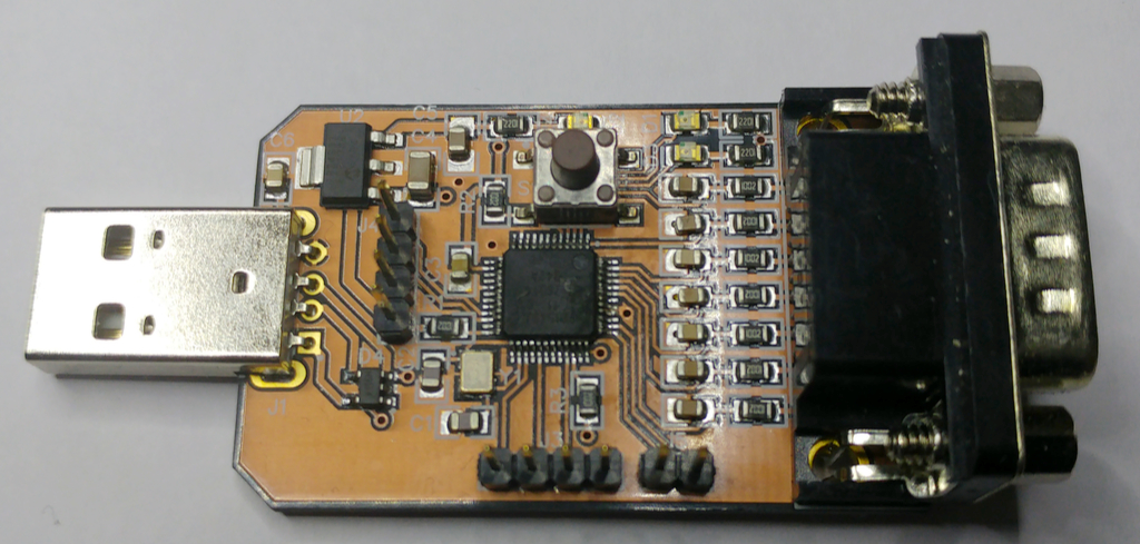
An adapter to connect a classic C64/Amiga joystick to a PC through USB. It's implemented using an LPC1549 controller and based on my more generic USB/Bluetooth USB joystick board.
It supports up to three buttons on the DB9 connector and additional four buttons with external pullups to be connected to the board connectors. The idea is to connect the four additional buttons of the "The C64" joystick which are needed to navigate in menus.
To switch between Amiga mode (where all buttons are low active, i.e. switch to ground) and C64 mode (where buttons 2 and 3 are high active as they are connected to POTX/POTY on the SID), press the SMD button on the PCB for one second. One of the LEDs indicates if the C64 mode is active (LED on) or not (LED off). Note that that the last setting is stored in an internal EEPROM, so it's automatically used until you switch mode again. Note that the button on the PCB is actually the ISP (in system programming) button. So if you press it while powering on the device, it will not connect as HID joystick but as USB drive where you can change the firmware by deleting the "bin" file and copying another bin to it. Use this with care though and only reprogram binaries meant for this specific device.
To also work on a "The C64", the HID descriptor mimics that of the "The C64" joystick.
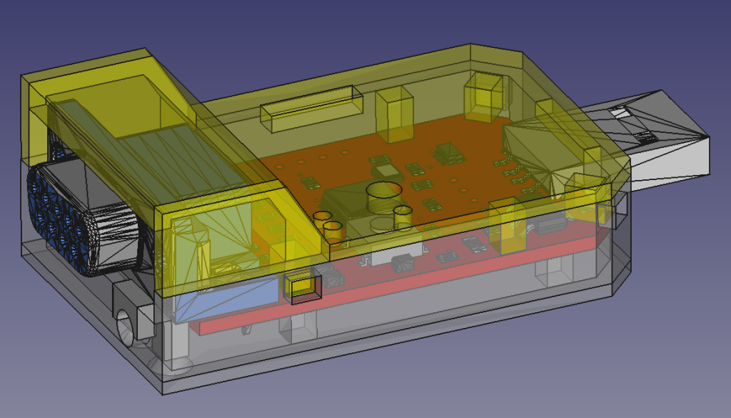
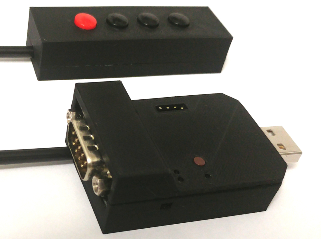
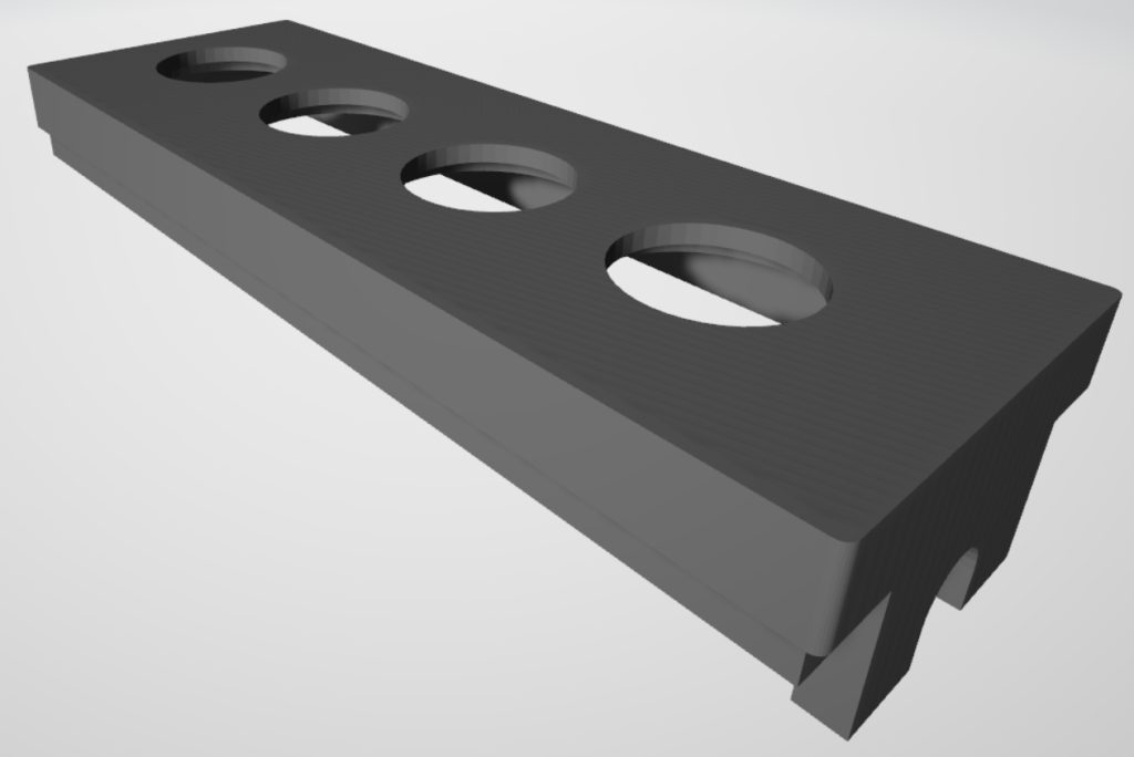
I designed a 3D printed case for it. It's very far from perfect, but for the moment, it's good enough for me:
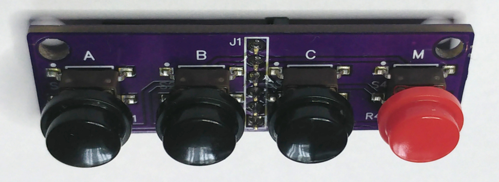
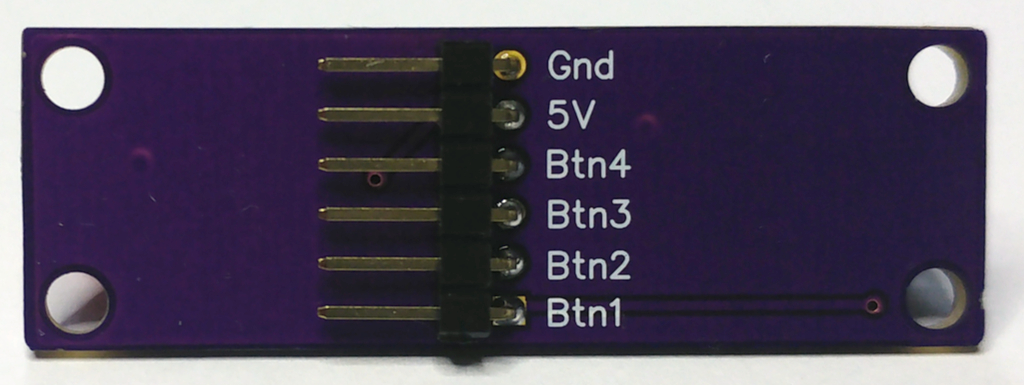
I designed an additional board for the four buttons used in menus on the "The C64".
Simple panel to fit into a Strapubox USB 1:
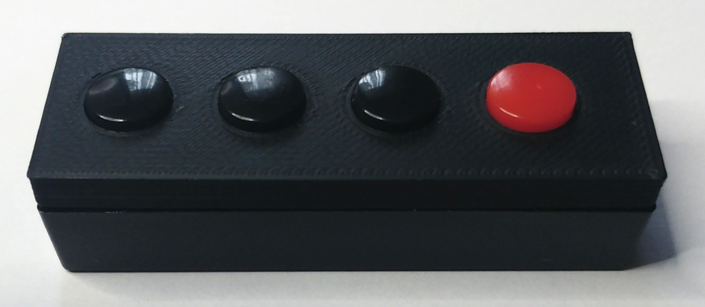
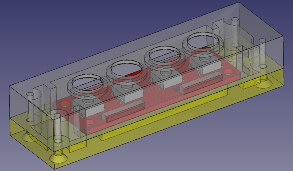
More sophisticated full case using self tapping screws:
This PCB can be connected to the UART and I2C headers on the main PCB where Tx is Button 5, Rx is Button 6, SCL is Button 7 and SDA is Button 8 (also ground and 3V3 have to connected at the UART connector). There is an automatic detection for these four additional buttons A weak pulldown is configured for button 5 (P0.13))after reset to check the presence of the external pullup. Only then, the buttons 5,6,7,8 are actually enabled (note that button 4 never exists). The activation of the four additional buttons is indicated by the 2nd LED.
All files related to this project can be found in the BitBucket
repository
https://bitbucket.org/fade0ff/c64_joystick_adapter
This is a spare time project I did without any commercial interest.
Everything is released under the Creative
Commons CC-BY license.

In a nutshell this means that you can do share, modify and use
everything released under this license even for commercial projects.
You just need to give me appropriate credit, indicate what changes you
made and agree not to try to force a more restrictive license on my
work.
See the CC BY license for details.