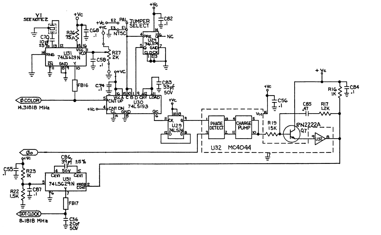
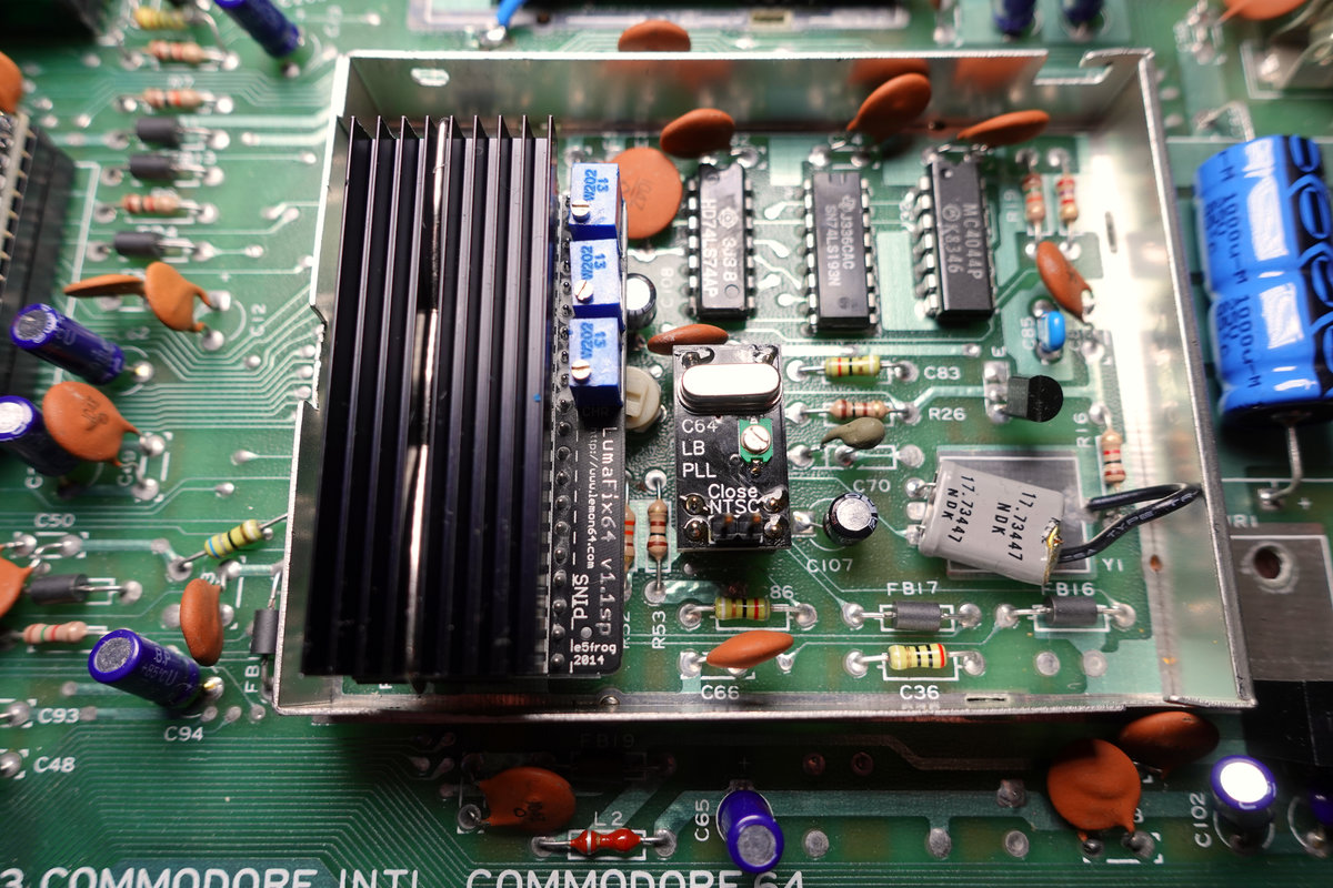
The clock circuit in a C64 generates the clock "Phi Color" (needed for PAL/NTSC color bursts) from a crystal oscillator and then creates a downscaled "Dot Clock" using a PLL and a divider. Actually, in the original "Breadbin" C64s, there were four ICs involved in this: the voltage controlled oscillator (VCO) 74LS629N (U31), the 4-bit counter 74LS193 (U30), the phase-frequency detector MC4044 (U32) and the dual Flip-Flop 74LS74 (U29).
In the later boards used in the C64C, this circuit was replaced by a single custom IC called the MOS8701.
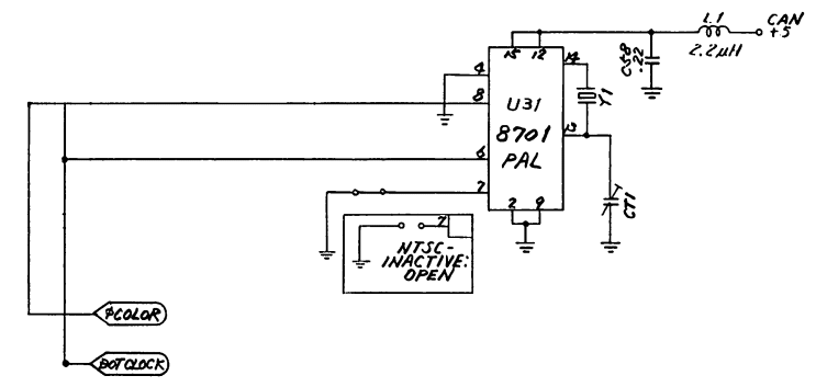
The main functionality is the same though
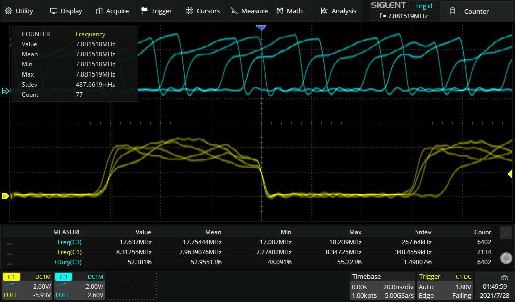
Now, the old circuit consists of a lot of parts which makes it also somewhat error prone. Besides, the MC4044 becomes difficult to get. The MOS8701 is a custom part that isn't produced since the 90s. So it can be only obtained by salvaging it from old boards. Besides, both circuits are not really able to create a low-jitter dot clock for today's standards. E.g. this is what the output of the MOS8701 looks like

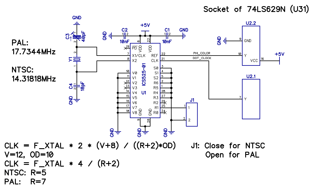
Anyway, even today, designing a low jitter PLL circuit isn't totally trivial, but thankfully there are integrated PLL circuits available. One that specifically fits this purpose is the ICS525-01 ("configurable clock") produced by IDT/Renesas. Now, there are already several replacements for the MOS8701 based on the ICS525-01, but AFAIK nobody created a replacement for the longboard clock circuit yet.
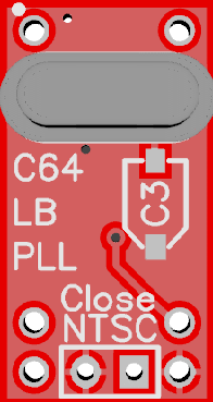
Now, as stated before, there are four ICs involved in the clock creation, but in the end, both, the color clock and the dot clock are connected to output pins of the the VCO 74LS629N. Actually, also the crystal oscillator and the trimmer are connected to the 74LS629N but as the resistive trimmer can't be used with the ICS525-01 and actually providing a completely autonomous clock circuit seemed like a good idea, I decided to also include the crystal oscillator and a capacitive trimmer on the replacement circuit. In a nutshell, the replacement circuit just takes the voltage supply from the 74LS629N socket and provides the two clock signals. All the other parts of the original clock circuit aren't used anymore.
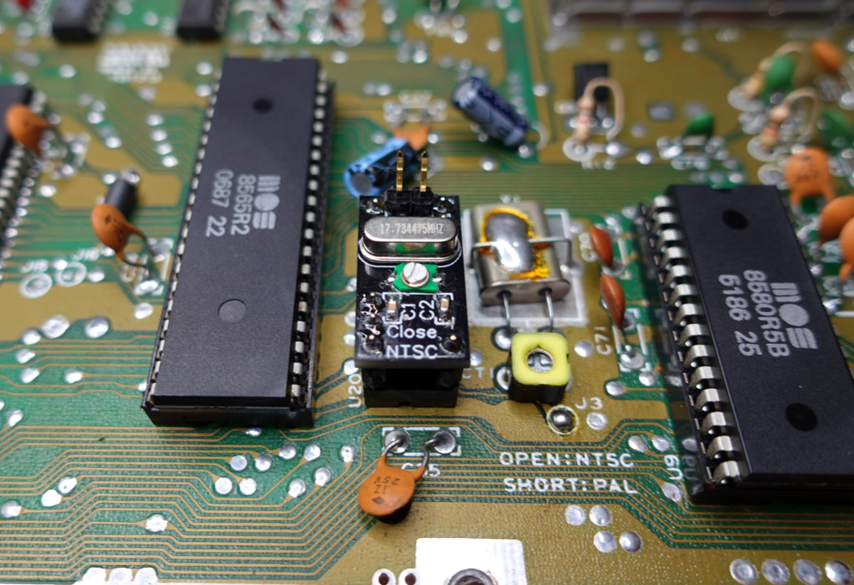
Note that in the original board, there is a jumper to select between PAL (divide by 9) and NTSC (divide by 7). However this PAL/NTSC selection is not available at the socket of the 74LS629N. So, to make the circuit usable for PAL and NTSC (with a different crystal oscillator of course), I also placed the jumper on board. Note that for the PAL version, you don't need to place the jumper at all and for the NTSC version, I would recommend to just shorten the pads with a piece of wire. For my tests, I actually soldered a pin header there to be able to test both divider settings.
Anyway, this is what I came up with:
Of course the goal was to make the replacement more or less the same size as the 74LS629N, so it will fit even if there is a Lumafix (or similar) installed on the VIC. To achieve this goal, I had to place SMD components on both sides. I usually try to place components only on one side, but in this case I think it's worth it to get a minimum size and avoid issues with nearby components on the board.
Before I dared to place this circuit into the precious breadbin from my childhood, I did some external measurements.
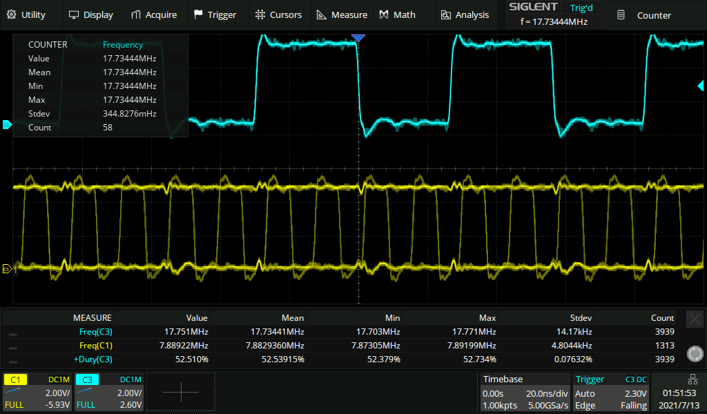
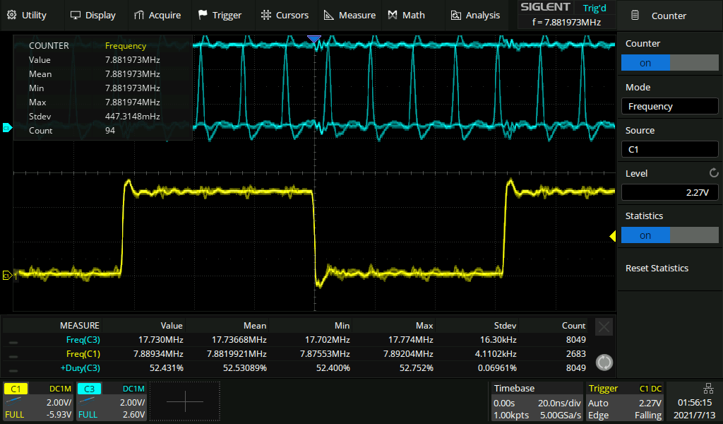
I was able to trim the frequencies nearly perfectly and everything looked fine, so I dared to place it in my breadbin (250407).
And as expected, it worked at first try.
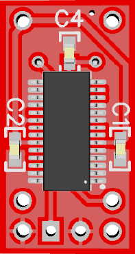
While I was at it, I also designed MOS8701 replacements for newer shortboard revisions. In this case, the external crystal and capacitive trimmer can be used so I decided to design two versions: an autonomous one with crystal, trimmer and PAL/NTSC jumper on board:
... and another one which uses the crystal, trimmer and jumper from the board:
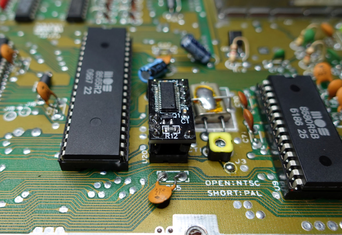
Note that this last version needs a small N-FET transistor to invert the jumper selection. For the PAL version, you can actually leave it (and the resistor) unplaced.
All files related to this project can be found in the BitBucket
repository
https://bitbucket.org/fade0ff/c64-pll-replacement
This is a spare time project I did without any commercial interest.
Everything is released under the Creative
Commons CC-BY license.

In a nutshell this means that you can do share, modify and use
everything released under this license even for commercial projects.
You just need to give me appropriate credit, indicate what changes you
made and agree not to try to force a more restrictive license on my
work.
See the CC BY license for details.