This is an add-on board for the 250466+ board which allows to perform normal and hard resets and to switch between eight Kernals, four SID2 addresses and swap the joystick ports by keyboard presses instead of onboard jumpers.
I liked the idea to hide the SMD components at the bottom side to not disturb the vintage through hole component glory of the C64.
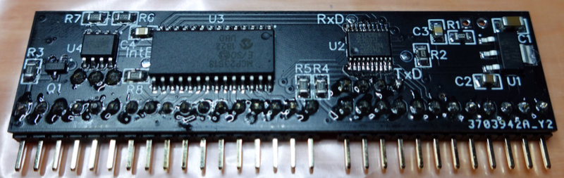
Yeah, yeah, I know, flux residue all over the place. I suck at cleaning PCBs.
If RESTORE is pressed down longer than 500ms, the LEDs are switched off and there is a keyboard scan performed. Releasing RESTORE ends the keyboard scan and switches on the currently active LED.
If one of the supported keys (the four functions keys, the two cursor keys, DEL and RETURN) is detected during the keyboard scan, the according function is selected and confirmed by a blink code on the bicolor LED.
If DEL is pressed during the keyboard scan (initiated by pressing RESTORE for > 500ms), the joystick ports are swapped. The swapping is confirmed by a single blinking of the originally active LED followed by a single blinking of the other LED. After releasing RESTORE, the permanently active LED is switched to indicate the port switch. I.e. if LED1 of the bicolor LED is red and LED2 of the bicolor LED is blue, red/LED1 means that the joystick ports are not swapped while blue/LED2 means that the joystick ports are swapped. Note that there is no reset.
Pressing the cursor keys during the keyboard scan switches the address selection lines A5_SEL and A8_SEL for SID2. This allows to select the four addresses 0xD400 (dual mono), 0xD420, 0xD500 and 0xD520. "Cursor Right" toggles A5_SEL and "Cursor Down" toggles A8_SEL. A change of the SID2 address will be confirmed by a blink code on the 2nd LED. Blinking once means 0xD400, twice means 0xD420, three times means 0xD500 and four times means 0x5D20. No reset is performed.
The three address lines A13/14/15 on the 64kB Kernal (E)EPROM are used to select between 8 Kernals. The four function keys are used to select four different Kernals. To access the remaining four Kernals, pressing the same function key again, toggles between the "lower" and the "higher" kernal. I.e. if you currently selected the first Kernal (F1) and use F1 again, you select the 5th Kernal (and vice versa). Accordingly, F3 lets you select Kernal 2 and 6, F5 lets you select
Kernal 3 and 7 and finally, F7 lets you select Kernal 4 and 8.
After each detected change, the current selection (1..8) is used to blink the first LED. E.g, if you selected Kernal 7, the LED will blink 7 times. As soon as RESTORE is released, a reset is performed and the Kernal is switched.
Note that to allow multiple selections and reduce NVRAM write cycles, the new configuration (for all the functions) is only actually used (and stored) after releasing RESTORE. Therefore, the reset after a Kernal switch is also only performed after releasing RESTORE. Besides, releasing RESTORE also switches on the currently active LED again, so a delayed releasing of RESTORE is helpful to read the blink codes.
If RESTORE is pressed for 3s without any other activity (key presses or blink codes) and then released, a normal RESET is performed.
If RESTORE is pressed for 5s without any other activity (key presses or blink codes), a hard reset is performed without releasing RESTORE.
As mentioned before, only the joystick port swap is permanently displayed by the color of the bicolor status LED. To display the currently selected Kernal and SID address, the key RETURN can be pressed during the keyboard scan. This will result in first blinking the first LED for 1..8 times to indicate the selected Kernal followed by blinking the 2nd LED for 1..4 times to display the selected SID address.
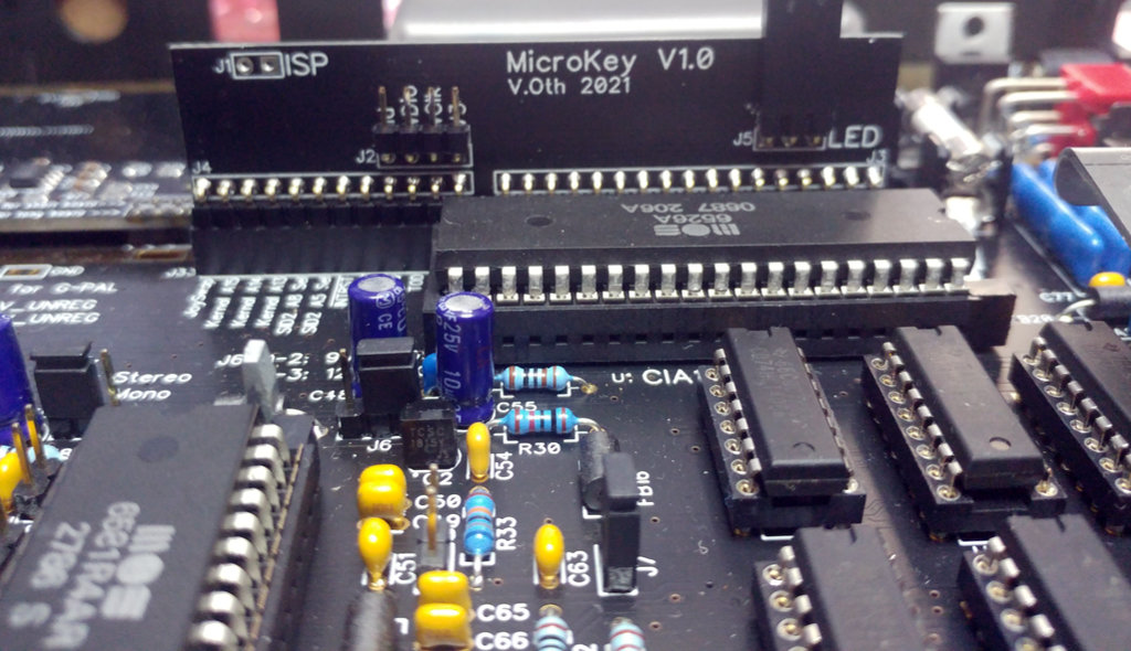
The MicroKey board sits on two mainboard headers/sockets which allow it to access all pins from the keyboard connector and the pins to select the Kernal, the SID and the joystick swap.
There are actually two connectors on the 250466+ board, but they are located next to each other, so the MicroKey board can access both.
In an nutshell, the Keyboard connector is used to scan the keyboard and the Microcontroller connector is used to switch the Kernals, SID address, joystick ports and perform a (hard) reset.
To perform the keyboard scan, a small
microcontroller, namely the LPC824
is used. It's a smallish Arm Cortex-M0+ controller in a TSSOP20 package with 16 general purpose pins.
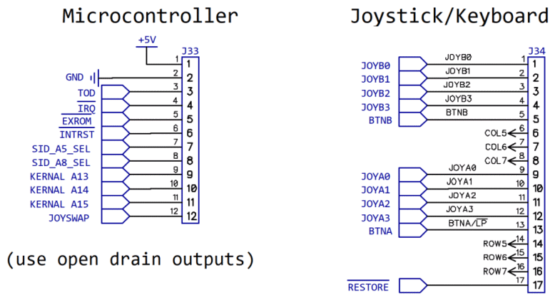
Note that all outputs, namely EXROM, INTRST, SID_Ax_SEL, KERNAL A1y, JOYSWAP and JOYB0 aka PA0_CTRL are implemented as open drain outputs, i.e. they can only pull the signal to ground and need a pullup on the mainboard.
The C64 internal signals like INTRST and EXROM are low active and have pullup resistors. The 250466+ specific signals SID_Ax_SEL, KERNAL A1y, JOYSWAP are designed in the same way: there are pullups on the board and you can either configure these signals by placing jumpers to ground or connect switches to ground. So when using the MicroKey board instead, it also just needs to switch to ground.
Now, the LPC824 has 16 GPIO pins where two of them are dedicated open drain pins which are fully 5V tolerant (i.e. you can apply 5V even if the controller is not supplied). All the other GPIO pins actually have push/pull stages and while they are 5V tolerant as well, this is only true when the controller is supplied. Therefore only the two dedicated open drain pins are used directly to control EXROM and INTRST. Since a third fast open drain output was needed for PA0_CTRL (aka JOYB0), this is implemented using
an additional N-FET transistor (IRLML2502).
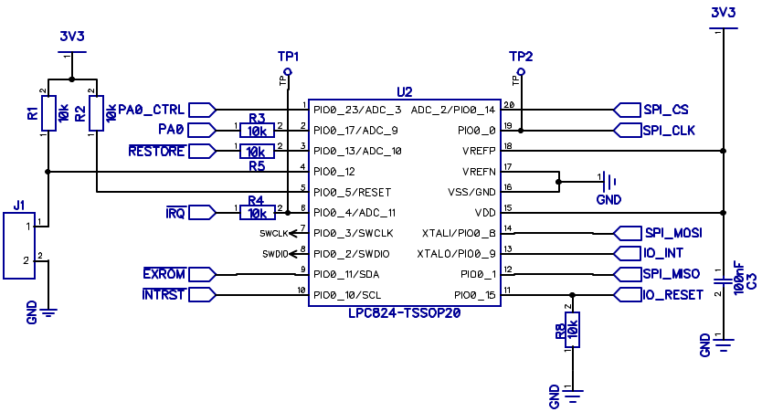
Three pins are used as input pins with a 10k resistor as input protection to read the signals RESTORE (low while restore key is pressed), IRQ (not actually used) and JOYB0 (to be able to monitor keyboard scans performed by the C64's CPU).
The remaining output and inputs pins are handled by an 16bit I/O Expander MCP23S18 which is controlled by SPI and uses open drain outputs. There are two 8bit ports on this expander. One port is configured as outputs to control SID_Ax_SEL, KERNAL A1y, JOYSWAP and two LEDs. The other port is configured as input to read the eight row signals from the keyboard matrix.
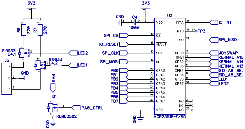
Note that the LEDs actually need a high side output. Therefore the dual channel P-FET Si9933 is used to convert the two open drain LED outputs from the MCP23S18 into highside outputs.
The C64 doesn't have dedicated hardware to scan the keyboard for key presses. The 64 "normal" keys of its keyboard are arranged in a matrix of 8 rows and 8 columns and these 16 lines are connected to an I/O chip called MOS 6526/8520 which is also known as CIA (Complex Interface Adapter). Note that there are actually 66 keys on the keyboard where the SHIFT LOCK key is just a mechanically locked version of the left SHIFT key and the
RESTORE key has its own line independent from the matrix (discussed later).
Anyway, the normal 64 keys are arranged in a matrix like this where the columns are connected to PortA of the CIA and the rows are connected to PortB.
| PB0 | PB1 | PB2 | PB3 | PB4 | PB5 | PB6 | PB7 | |
| PA0 | DEL | RETURN | Cursor L/R | F7 | F1 | F3 | F5 | Cursor U/D |
| PA1 | 3 | W | A | 4 | Z | S | E | SHIFT L |
| PA2 | 5 | R | D | 6 | C | F | T | X |
| PA3 | 7 | Y | G | 8 | B | H | U | V |
| PA4 | 9 | I | J | 0 | M | K | O | N |
| PA5 | + | P | L | - | . | : | @ | , |
| PA6 | £ | * | ; | CLR | SHIFT R | = | Arrow Up | / |
| PA7 | 1 | <-- | CTRL | 2 | SPACE | C= | Q | STOP |
Forgive me that PortA pins are rows in this table while the schematic calls them columns (as do I). Just imagine that rows and columns are switched ;)
When using the C64's built in command line interface or BASIC programming language, the keyboard scan is performed by the integrated operating system, also known as Kernal.
Note that while the way that the Kernal performs the Keyboard scan is a typical way, it's not the only way to do it. Actually quite a few games have a very different keyboard scan. Actually a game or demo can decide to not scan the keyboard at all.
I'll not go into much details, but also the joysticks lines are connected to PortA and PortB of the CIA. There is no matrix though, pushing a direction or button just pulls the according line to ground. So scanning the joysticks is generally possible without pulling any CIA ports low. Then again, scanning a paddle or mouse involves switching the POTX/Y multiplexer through PortA6/7. But that's another story.
Anyway, the Kernal keyboard scan is performed in the Kernal's IRQ routine which is triggered with 60Hz frequency also on PAL C64s. It configures the pins of PortA as outputs and the pins of PortB as inputs. The first thing it does is to pull all PA0 pins low to check if at least one key is pressed. If this isn't the case. it stops there. If a key is pressed (in the example F1 which is in row PB4), the routine pulls down each column PAx one after the other. This way, also multiple key pressed can be detected.

It's also worth noting that the Kernal always leaves PA7 switched low. The reasons for this is that the STOP key is in this column. So several routines in the Kernal can check if STOP was pressed outside of the normal keyboard scan.
Now, again, this is a typical way to scan the keyboard, but not the only one. Actually, a game can also decide to configure PortA as input and PortB as output. However, most games at least keep the convention to use PortA as output and PortB as input.
The background for this probably is that, as in its predecessor, the MOS 6522 aka VIA (Versatile Interface Adapter), the two ports A and B are not totally identical. While the CIA datasheet isn't very clear about this, PortA uses open drain outputs with fixed pullups (implemented through N-FETs) while PortB actually uses push-pull stages. But as the CIA is an NMOS device, not a CMOS device, the highside of the push/pull stage is
also an N-FET and therefore is pretty high ohmic even when active. Therefore the CIA manual talks of an "active" pullups.
This is why shorting one of the CIA Port pins to ground doesn't do any harm for either, PortA and PortX. As mentioned before, this is actually how joysticks work on a C64. They share lines with keyboard rows/columns and if you press a direction or button, the according line is switched to ground. Which also explains that joysticks interfere with the (Kernal) keyboard scan.
We already learned that the RESTORE key has a separate line and is not part of the keyboard matrix. Indeed, the RESTORE key on the C64 is not like any other key as its status can't be read. Instead, it's used to create a short low pulse on the NMI (not maskable interrupt) line. This is accomplished by using a Timer IC 556 configured as a one shot multivibrator (yes, that is a thing and no, this is not raunchy). The length of the NMI pulse is determined by R24 and C28 (~29µs).
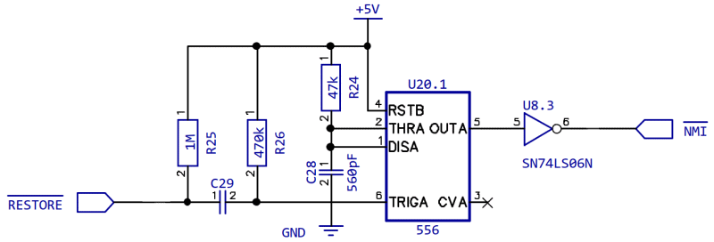
Also note that the RESTORE line is not directly connected to the trigger input of the 556. The capacitor C29 acts as a high pass filter. I.e. if you press RESTORE, there is a falling edge which leads to a short low pulse on the TRIG input.
I.e. it doesn't matter how long you press down the key, as the only thing that is really used is the falling edge created by pressing it down.
Side note: on older board revisions, the capacitor C29 was pretty small (51pF) which caused the NMI to be only raised if you smashed the RESTORE pretty key hard to create a falling edge with maximum steepness and minimum low level. For my 250466+ board, I suggested to use 2.2nF instead which also triggers the NMI if you press down RESTORE "normally".
Anyway, what is important here is that RESTORE is not only an independent key that is not part of the keyboard scan but also the C64 can only detect that it was (shortly) pressed and can't know if it was released or not. An external circuit reading the state of the RESTORE line directly is not limited like this of course. This makes the RESTORE key the ideal candidate to initiate special functions when pressing it down longer. This is not a new idea of course, so I borrowed it from other Kernal switchers
and the like. The idea is that pressing down RESTORE for e.g. 500ms is used as indicator to begin looking for special key presses to switch functions. Also pressing it down a few seconds can be used to initiate a reset or a hard reset.
Now what we learned from the analysis of the keyboard scan on the C64 is the following
So, while it would be possible to implement a passive keyboard scan that just watches the CIA port pins, this can only work if there actually is a full keyboard scan performed and it is known exactly how it is performed. Both is only the case for the Kernal keyboard scan. It would work in a few games, but wouldn't work in lots of common games and could even cause erratic key detections (by the sniffer) in quite a few. Besides, a passive scan would involve some tricky
timing as the PortB pins can only be interpreted correctly within the <=200µs in which a single PortA line is pulled low.
The alternative is an active keyboard scan, i.e. pulling PortA pins low and measuring PortB pins independently from the C64. While this is possible of course, it would need 16 analog switches and these would have to be located on the mainboard or in a separate adapter between mainboard and keyboard. Now to be frank, I didn't think of this when designing the first revision of the 250466+ board, but I honestly don't think there is enough space on the board to switch 16 analog channels with DIP ICs (e.g. a 74HCT4066
is a 14 pin DIP and can only switch four lines). And putting the analog switches into an additional adapter would require additional wires or a changed keyboard connector. Besides, normal analog switches like the 74HCT4066 add another 20-100Ohm resistance into the keyboard lines which is not ideal.
However, while a 100% solution would come at a cost, a 99% solution is fairly simple. Since it's safely possible to pull down PortA pins externally even with the CIA still connected, it is also possible to perform an active keyboard scan without disconnecting the CIA from the keyboard matrix. There are some limitations, of course. Firstly, while there are ways to minimize interference with the internal keyboard scan (to avoid erratic detection of key presses), there's no way to avoid the internal
keyboard scan from detecting the keys pressed during the external keyboard scan. Secondly, as the Kernal switches PA7 to ground outside its own scan and we want to perform our scan outside the Kernal scan to avoid interference, we can't distinguish the keys pressed in the column connected to PA7 from keys in other columns. In a nutshell, we can either only use the keys in this columns or lose the pins in the column.
In the end, I decided to use only the keys connected to PA0, namely the four functions keys, the two cursor keys, DEL and RETURN. This makes the active keyscan much easier and decreases the chance of conflict with a non-standard keyboard scan routine. So, in a nutshell, this is how the keyboard scan performed by MicroKey works
There are some bells and whistles to avoid interference with the Kernal keyboard scan. I.e. PortA0 is used to raise a rising edge interrupt which reloads a delay counter to avoid that the active scan happens at the same time as the internal scan. Since a very high frequent toggling of some game specific polling routine could delay the active scan infinitely, there is a blocked detection etc. The code is a bit of a mess due to all of these debounce and delay counters, so I won't discuss every detail here.
The MicroKey can perform normal internal resets for two reasons: firstly, switching the Kernal without performing a reset could lead to an undefined CPU state (i.e. one opcode ist fetched from the old Kernal and the next one for the new Kernal etc.). This is also important for configuring the last selected Kernal after a cold start. Secondly, MicroKey is about avoiding case modifications etc., so being able to perform a reset without a dedicated switch is just very handy.
Now, performing an internal reset is very easy as it just involves pulling down the INTRST line low for 200ms. So, what is a hard reset and why would anybody want one? To answer this, first let's have a look at the (Kernal's) reset procedure.
After a reset, the Kernal checks if it can detect the string "CBM80" at the address 0x8004. If the string is detected, the two bytes at 0x8000 are interpreted as reset vector and jumped to. The idea is that the string "CBM80" indicates the presence of a ROM module attached to the expansion port which is mapped into an 8kB RAM page at 0x8000 by pulling EXROM low on the expansion port. Now, back in the 80s this mechanism was misused by to implement a reset protection. The according programs just put the string "CBM80" in the RAM at 0x8004 and put the address of some internal function (typically program restart) at 0x8000. So when causing a reset by pulling INTRST low, the program would shortly lose control but the Kernal would call the program's reset handler instead of performing its own.
Now, the idea of a "hard" reset is to pull EXROM low a bit longer than INTRST. This temporarily maps a non-existing ROM module into the 8kB page at 0x8000. So the Kernal can't see the CBM80 string in the RAM at 0x8004 because it just reads nonsense from the expansion port. Therefore it continues with its own reset routine and the reset protection is circumvented.
The typical time for the EXROM delay is 200ms which works fine for the normal Kernal. Alternative Kernals like Speed DOS have a slightly different timing, so they may have already started the RAM check while EXROM is still low. This leads to an 8kB page missing and so instead of "38911 BASIC BYTES FREE", only 30719 bytes are reported. While I'm not sure that there is an EXROM delay that works for every possible Kernal, at least the software controlled EXROM line allows exact control over the
timing. Note that there actually is a hard reset circuit on the 250466+ board, but it's implemented as HW delay which is neither very exact nor can it be changed easily.
All files related to this project can be found in the BitBucket
repository
https://bitbucket.org/fade0ff/microkey
This is a spare time project I did without any commercial interest.
Everything is released under the Creative
Commons CC-BY license.

In a nutshell this means that you can do share, modify and use
everything released under this license even for commercial projects.
You just need to give me appropriate credit, indicate what changes you
made and agree not to try to force a more restrictive license on my
work.
See the CC BY license for details.